

A porch lamp can spoil a telescope image without appearing in the frame. Light entering from the side can strike the inside of a dew shield and bounce toward the optics, adding flare or a glow over faint detail.
Telescope baffles break those reflected paths. Their internal rings shade the walls and hide illuminated surfaces from the lens. That is why their value continues after a plain tube has already blocked the straight path from a troublesome light source.
We’ll use a Celestron C8, the familiar 8-inch Schmidt-Cassegrain, to explain the geometry. The worked example compares an open telescope entrance, a smooth dew shield and the same shield with six baffles. It follows both direct and reflected light.
What the ray tracing shows
At the sampled 20–85° source angles, the six baffles reduced wall-reflected light reaching the telescope entrance by about 35–97% compared with smooth walls, depending on angle and assumed finish. At the steeper 50–85° samples, both shields blocked every sampled direct path, yet adding baffles still reduced the reflected component by about 35–67%. That is the benefit a direct-blocking chart alone would miss.
| Tested source angle | Less wall-reflected light with baffles |
|---|---|
| 20° | About 87–97% |
| 40° | About 66–71% |
| 60° | About 48–54% |
| 80° | About 35–38% |
| 85° | About 64–67% |
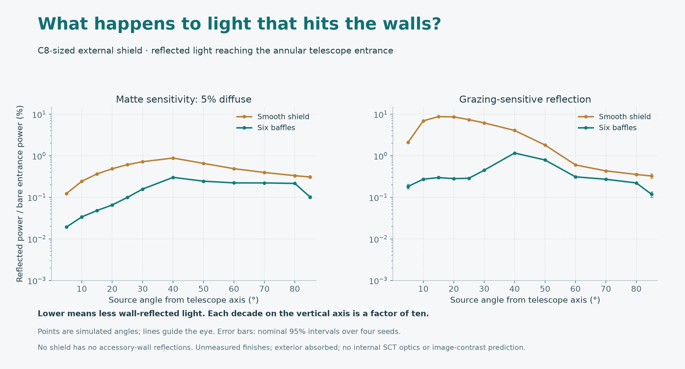
Each table range spans the two surface models at that angle. The improvement varies with direction; it does not increase steadily toward the side. The full sweep also exposes a tradeoff: under exactly on-axis illumination, the vanes add a small reflected component of about 0.009–0.010% of bare-entrance power, whereas the smooth shield adds none in this model. The useful direct field remains clear.
These results describe light reaching the model’s telescope entrance. They do not predict the brightness of a finished image: the corrector, mirrors, internal baffle tubes and camera are outside this external-shield study. The surface finishes are stated assumptions, so the comparisons explain the mechanism without presenting simulated percentages as measurements of a coating or a commercial shield.
How a ring stops light that a tube can miss
Imagine shining a lamp into an empty black tube from an angle. The tube wall blocks many straight paths, but the illuminated patch inside can still be visible from the far end. Black material absorbs much of the light; it does not absorb all of it.
A baffle projects inward from that wall. Put it in the right place and it screens the bright patch from the telescope entrance. Other paths encounter another surface before reaching the optics, giving the dark finish another opportunity to absorb light. NASA’s discussion of baffle design describes this in terms of which surfaces a source illuminates and which of those surfaces the optical system can see. Baffle design principles
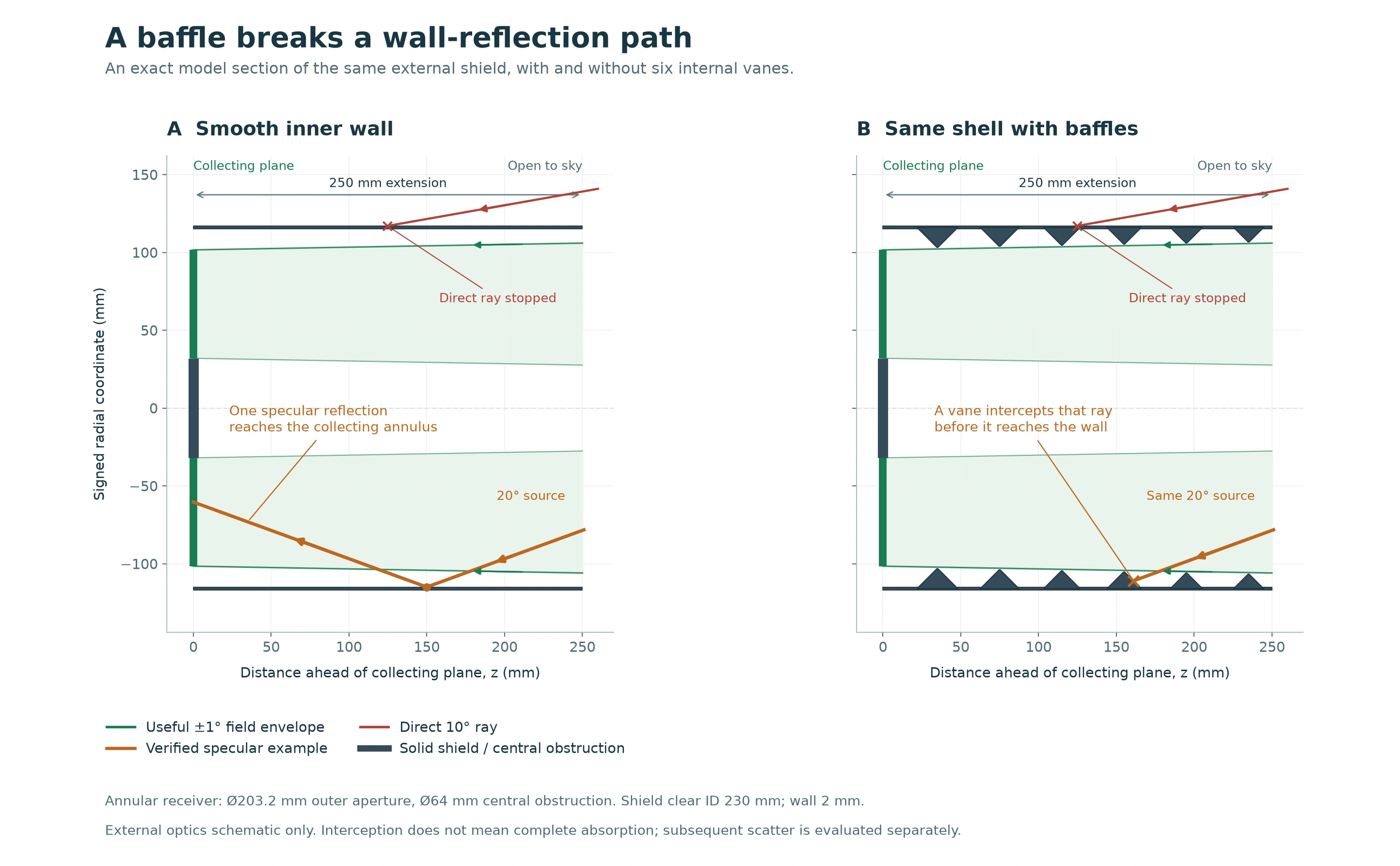
The cutaway shows the external shield. An SCT already has internal baffling around its folded optical path; the rings discussed here sit in front of the telescope.
The vane faces matter as much as the holes. A bright baffle face can itself become a source of scattered light. Changing a slope, spacing or finish can help one route while opening another. Ansys’ telescope stray-light example illustrates why geometry and surface scattering need to be studied together.
A C8-sized example with its assumptions visible
Celestron specifies a 203.2 mm aperture, 2032 mm focal length and 64 mm secondary obstruction for the standard C8. The secondary blocks the center, so our receiving area is an annulus rather than a solid disk. Official C8 specifications
For the illustration, we chose a 230 mm clear shield diameter, 250 mm extension ahead of the entrance plane, and six vanes. These are the dimensions of our teaching model, not measurements of Celestron’s retail dew shield. The smooth and baffled versions share the same outer geometry and finish; only the vanes change.
Both receive the same uniform directional illumination. The bare entrance is included as a control. The calculation follows repeated surface interactions and keeps received, absorbed, escaped and unresolved energy separate, rather than declaring a ray absorbed as soon as it hits a baffle.
The first finish scatters 5% of incident light diffusely and absorbs the rest. The second adds a directional reflection term that grows at grazing incidence. We apply the same assumed finish to the interior of each shield, with the exterior and rims absorbing. This is a sensitivity comparison, not a measurement of black plastic, paint or flocking.
Higher angles: separate direct light from reflections
A direct ray reaches the entrance without touching a wall. A reflected ray gets there after at least one surface interaction. Those are different routes, and plotting only the first can hide much of what the baffles do.
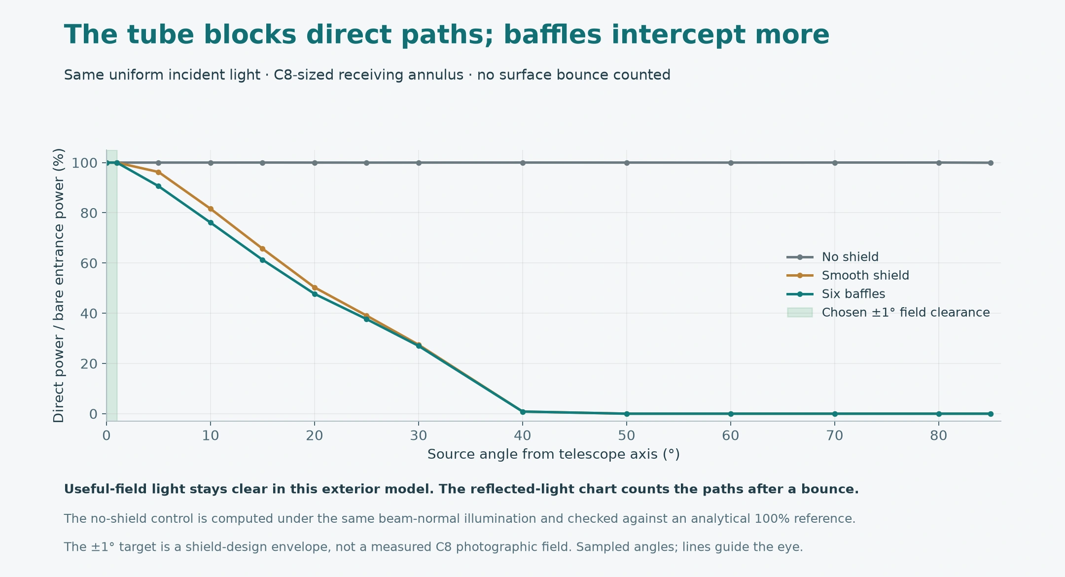
At 20°, direct light reaching the entrance falls from approximately 100% without a shield to 50.3% with smooth walls and 47.7% with baffles. The tube provides most of the direct screening here. In ideal circular geometry its last straight path closes at about 41°; the sampled 50–85° shielded cases admit no direct rays, while the reflected-light comparison still shows a benefit from the vanes.
At a source angle where both shields block the straight route, their direct curves can overlap at zero while their reflected-light curves remain different. That is the reason to show both charts. It also explains why a narrow band of strongest added direct blocking should not be described as the entire useful range of a baffle.
Leave room for the light you want
Each baffle must preserve rays from the edges of the field, as well as the central target. Making every ring only as wide as the telescope aperture would clip those tilted bundles.
For a circular entrance of radius a, a baffle a distance z ahead needs a clear radius of at least a + z × tan(half-field angle), before alignment and manufacturing allowances. The further forward the baffle sits, the larger its opening must be.
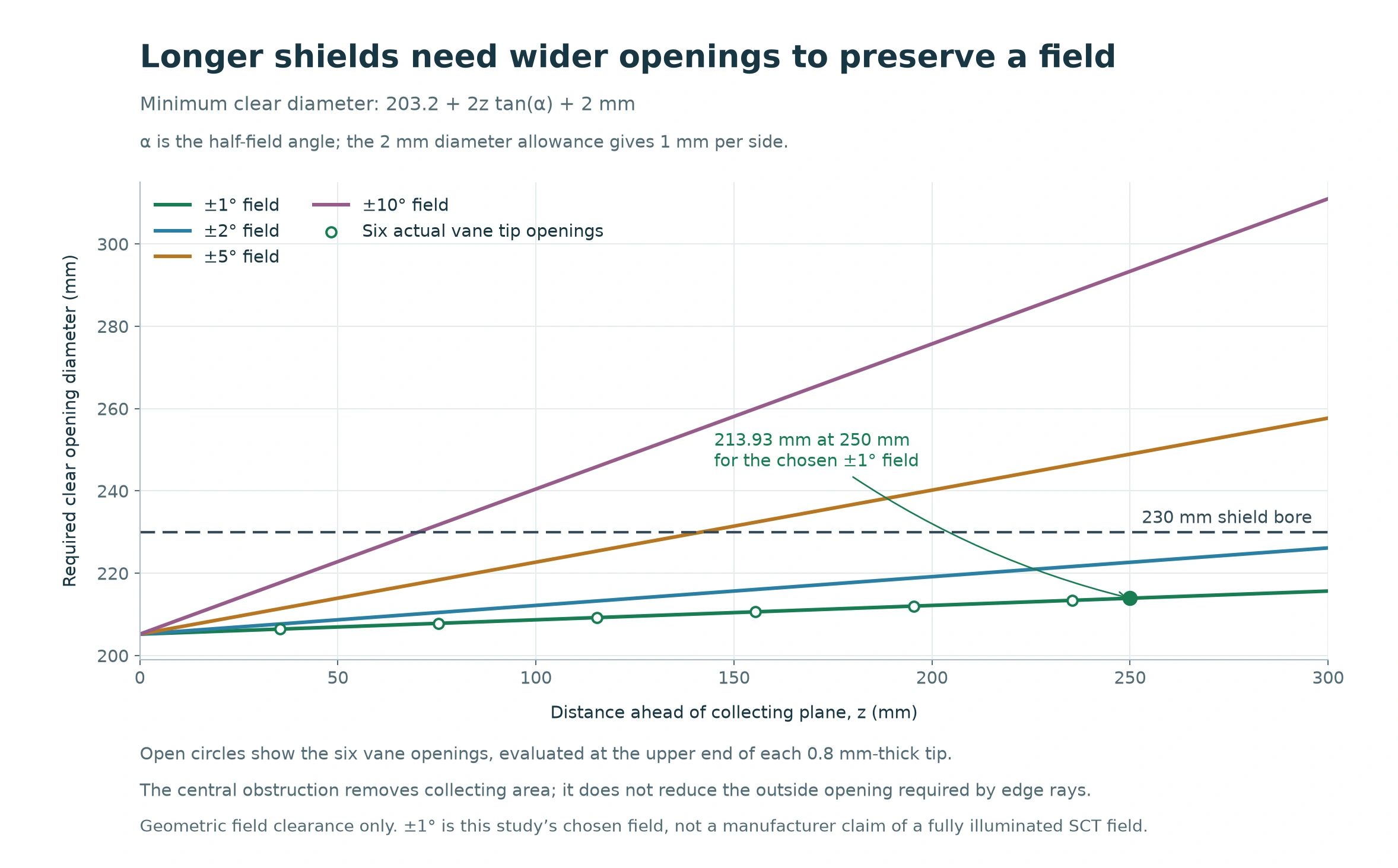
Our model uses a deliberately generous ±1° external clearance target, plus 1 mm radial allowance. That is a 2°-wide envelope for the shield design, not a promise that the C8 delivers a fully illuminated 2° photographic field. The eyepiece or sensor, focal configuration and internal telescope geometry determine the actual usable field.
At 250 mm ahead of the assumed entrance, the target requires 213.9 mm clear diameter including that allowance. Every finite vane profile clears that envelope. A separate sensitivity check also keeps a 20 mm pupil setback and 0.5 mm radial decenter clear, with about 0.15 mm of the modeled radial reserve left.
Does a 6-inch SCT benefit more than an 8-inch?
Aperture alone cannot answer that. If a telescope entrance and shield are scaled together, ray angles and the proportions of the shadowed regions stay the same. Shield length relative to aperture, central obstruction, vane profile and reflectance determine the comparison.
A C6 can therefore benefit from the same principles. The C8’s specified aperture and central obstruction make it a straightforward worked example.
Dew protection and light pollution
The surrounding shield also reduces the corrector’s exposure to the cold night sky, slowing radiative heat loss and helping delay dew. That thermal benefit is separate from the baffles’ control of reflected light. Celestron’s own dew-shield explanation discusses both uses. An optical simulation cannot tell us how many dew-free hours to expect.
Baffles also cannot remove skyglow arriving from the same direction as the target. They screen unwanted routes into the telescope while preserving the field we want to observe.
Browse telescope accessories from StargazeWorks.
Study methods
The primary study traces 73.4 million rays over 14 source angles from 0° to 85°, with four seeded runs per condition and up to 32 interactions. The rotationally symmetric design is represented by 256 angular facets. The source is a uniform directional beam whose launch rectangle covers the shield and bare entrance; power is normalized to the projected annular collecting area at each angle.
Independent checks cover the annular receiver, analytical smooth-tube transmission, field clearance and energy accounting. Grid refinement, a larger source footprint and a longer interaction limit test numerical sensitivity. The small on-axis increase remains in the complete data. These are external geometric-optics results under assumed reflectance laws; they do not establish measured image contrast or performance at exactly 90°.